IR2 Facility
Ion iRradiation with In-siru electrical Resistivity measurement
 Introduction
A short description of IR2
Example of operation
Specifications
Results - Publications
People
Image gallery
Introduction
This specialized irradiation facility is used for radiation damage studies of metallic materials. It allows irradiation of samples at well controlled flux and temperature, from the cryogenic range up to 700 K, by means of a dedicated cryostat. Furthermore, the electrical resistivity of the sample can be measured in-situ during the irradiation. In metallic materials the electrical resistivity is very sensitive to the presence of defects, such as those created by the irradiating particles. In this way the damage created in the sample by the impinging particles can be quantified during the irradiation allowing detailed systematic studies to be performed in a relatively short time.
The facility has been developed within the Hellenic National Fusion Research Program for the study of radiation damage in fusion technology materials. It is installed at a beam line of the NCSR "Demokritos" 5MV TANDEM accelerator.
A short description of IR2
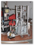
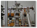
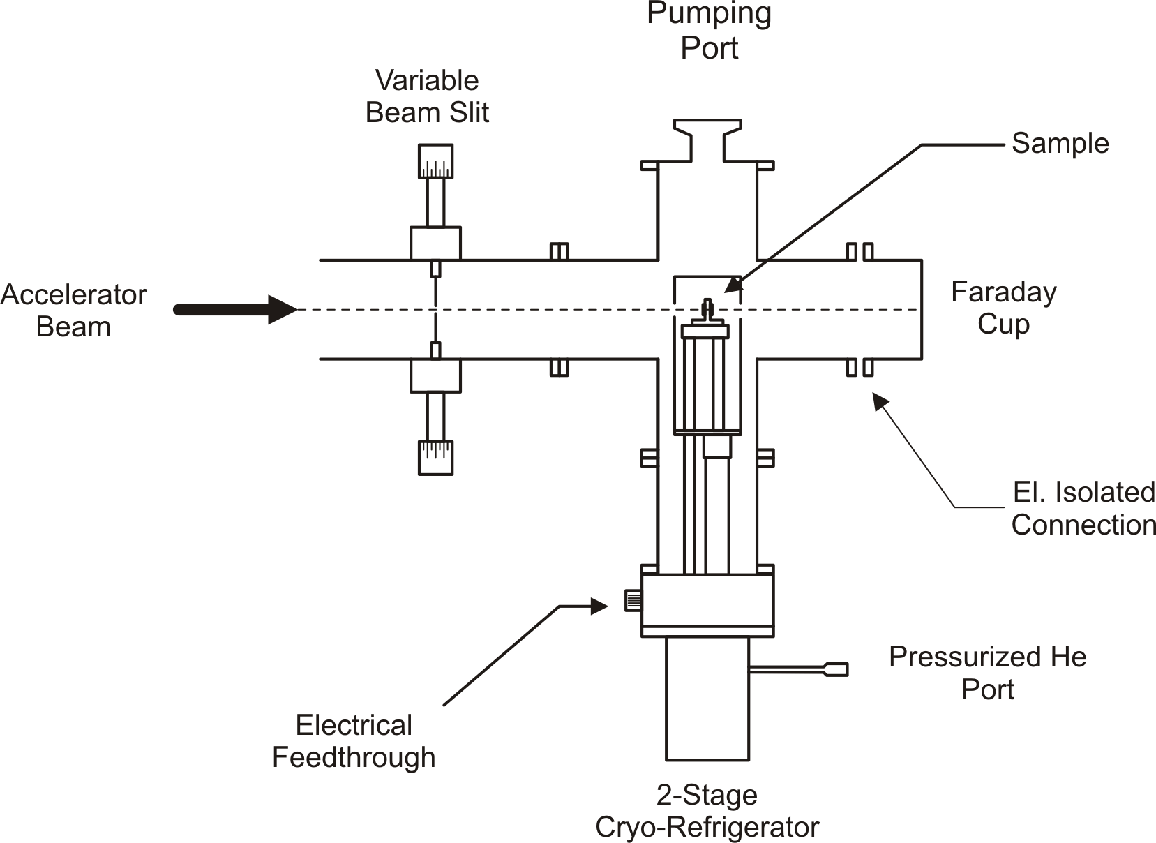
A schematic drawing of the IR2 beamline is shown in the figure below. The dimensions of the ion beam are defined by a variable slit collimator. The sample is held in the beam, attached to the cold-finger of a 2-stage, closed-circle He refrigerator, capable of attaining temperatures down to 10 K. The cryostat is integrated in the vacuum of the beamline. Electrical connections to the sample are provided through an electrical feedthrough at the base of the cold-head. A Faraday cup positioned at the end of the beamline is used for measuring the beam current.
Example of operation
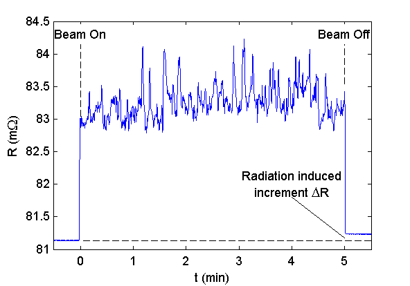
The graph below shows the resistance trace of a sample (a foil of Fe-Cr alloy) as the ion beam is switched on for 5 minutes and then switched off. The sample is held at a temperature of 20 K. When the beam is switched on the resistance of the sample increases suddenly due to beam heating. The fluctuations in the resistance are due to short-time variations of the beam current. This effect can be used to estimate the actual sample temperature during irradiation (in this case it was 40 K). After beam off the resistance returns to a value slightly higher than the initial. This small increase in resistance is due to the damage created in the lattice of the sample by the ion beam.
IR2 Specifications
| Accelerator | 5 MV Tandem |
| Particles | H, D, He and light ions up to O |
| Beam dimensions | up to 1 × 1 cm2 |
| Beam current | up to 1 micro-amp protons |
| Sample temperature | 10 - 700 K |
| Electrical resistance resolution | 10-7 Ohm |
Results - Publications
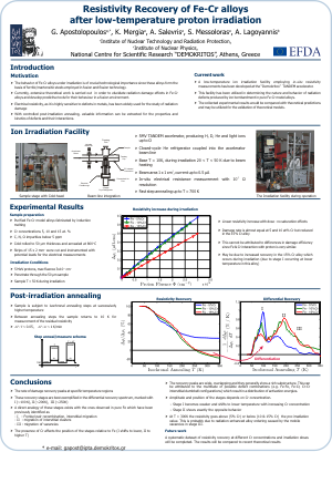
- Resistivity recovery of Fe-Cr alloys after low-temperature proton irradiation, poster presented at the Ion irradiation workshop, Oxford, September 2011
[Download PDF]
People
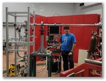
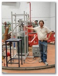
A number of people have collaborated for the development and installation of IR2.- Spyros Messoloras (INRASTES)
- Dina Mergia (INRASTES)
- Tasos Lagogiannis (Tandem Lab)
- Antonis Salevris (Technician)
- Zoi Kotsina (PhD student)
Image Gallery
Click a picture to see a larger view.